Grab a 10 × 15 grid of 150 addressable LED modules, a USB‑C‑powered ESP32 MagWLED‑1 controller, a 12 V supply sized for ~45 A, and a 3 mm frosted acrylic sheet for diffusion. Solder the LEDs in a snake‑pattern, label each pad, and wire data, 5 V, and GND consistently across rows. Flash the firmware via USB‑C, set the controller to 12 V mode, pair it with the Android app over Bluetooth, then mount the diffuser and secure everything with spacers or hot glue. Follow the steps and you’ll get a bright, programmable desk surface ready for further customization.
Essential Materials for a DIY LED Desk
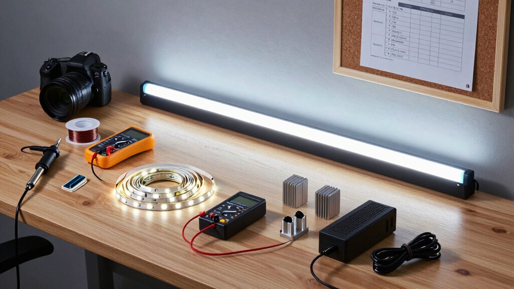
Where do you begin? You gather the 150 addressable LED modules, each ready to be soldered into a 10 × 15 grid, and the ESP32‑based MagWLED‑1 controller that powers them via USB‑C. Pick a 3 mm frosted Perspex or diffused acrylic sheet for the top; its diffusion smooths the light, eliminating hotspots. Grab the electronics box, a USB‑C/USB power adapter, and a sturdy LED connector to link the grid to the controller. You’ll also need a USB cable for firmware uploads, a set of soldering tools, and a reliable Bluetooth‑enabled Android app for wireless control. Finally, keep a DIY manual on hand to follow the snake‑pattern wiring of data, 5 V, and GND, and to test everything before sealing the desk. The system can also benefit from RGBIC‑style segmentation so you can run multi‑color effects across different sections of the grid for richer lighting RGBIC technology and synchronized music or game audio to boost immersion.
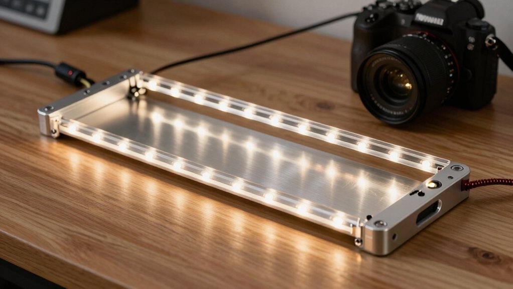
Assemble LED Desk Frame and LED Grid
Ready to bring the desk to life? Start by assembling the frame, then lay the LED grid inside. Solder 150 addressable LEDs into ten rows of fifteen, labeling each pad as you go. Plan your layout with a sturdy beam-split structure to ensure even light distribution across the grid Best Monitor Integration. Cut fourteen 60‑mm wires per color for the snake data pattern, then route data, 5V, and GND connections between rows, keeping data flow consistent to avoid damage. After soldering each row, test the grid by powering the electronics box. Once the grid lights correctly, reinsert it into the table, align the LEDs, and secure the grid with hot glue or small spacers. Finally, pour a thin layer of epoxy resin over the frame’s underside to reinforce the structure before adding the top cover.
Wire LED Desk LEDs and Power Supply Safely
You’ll want to follow solid wiring practices by keeping data lines short, routing them consistently in the same direction, and using proper gauge for the +5V and GND connections.
Make sure your power supply is sized for the total current draw—calculate the load at roughly 30 mA per LED and leave headroom for spikes.
Test the whole system before final assembly to confirm correct data flow and uniform brightness across the desk.
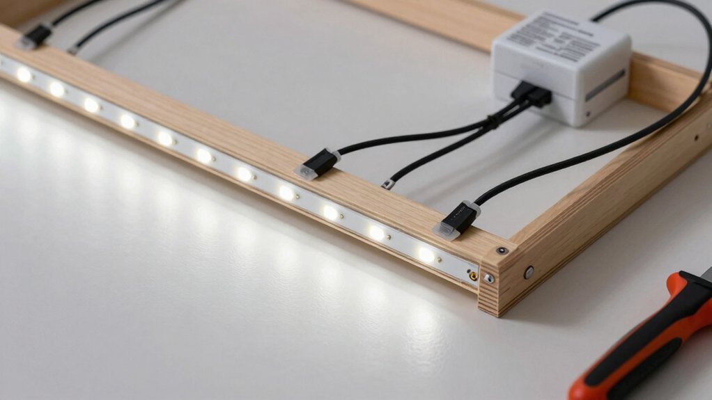
Consider using a cable management approach with adhesive clips that can secure wires along the desk edge to prevent tangling Cable Size Compatibility Across Clips.
Wiring Practices
Because the desk’s lighting grid spans several rows, you’ll need a clean data‑and‑power layout that keeps voltage drops and signal reflections to a minimum. Start by routing the 5 V data lines in a snake pattern, keeping all strips oriented the same way to avoid reverse polarity. Cut each LED strip at the factory‑marked lines, solder 60 mm segments, and label the pads so you can match rows during assembly. Run a dedicated +5 V bus on one side of the grid and a GND bus on the opposite side; this dual‑rail approach stabilizes voltage across the length. When you use 12 V strips, add proper current‑limiting resistors and verify the total draw stays within the PSU’s rating. Test the first LED from the electronics box, then expand row by row, checking data integrity and power distribution before finalizing the wiring. Integrate a surge‑protected power strip to safeguard the setup surge protection and ensure reliable power delivery across the desk.
Power Supply Sizing
A typical 12 V desk with 1,200 LEDs can pull up to 36 A if each LED runs at 30 mA, so you’ll need a power supply rated well above that—preferably 45 A or more—to keep voltage sag and overheating at bay. Additionally, plan for efficient wire management to minimize heat buildup and maximize airflow around the LEDs cable management. First, calculate the current budget: multiply 30 mA by the LED count, then add extra for RGBW channels if needed. Choose a supply that delivers the required voltage and a safety margin of at least 20 %. When you use a USB‑C PD controller, verify it can switch between 5 V and 12 V without dropping below the calculated current. Wire LEDs in manageable banks, adding a max‑power cap in firmware to protect the power supply. Finally, run a dry test to confirm voltage stability and heat dissipation before final assembly.
Upload Firmware and Connect via Bluetooth
Connect the MagWLED‑1 controller to your computer with a USB‑C cable and drag the firmware file onto the device to flash it.
Once the firmware’s loaded, power the desk and open the Android app, then enable Bluetooth on both the phone and the controller.
Follow the on‑screen pairing steps to link the app to the desk and start controlling your LEDs wirelessly.
Firmware via USB-C
The MagWLED‑1 USB‑C controller lets you flash new firmware directly from your computer, then instantly pair the desk with the Android app over Bluetooth for wireless control. Plug the USB‑C cable into the controller and your PC, launch the flashing tool, and select the appropriate .bin file. The ESP32‑based board detects the connection, verifies the file, and writes the firmware to its flash memory in seconds. You’ll see a progress bar and a confirmation once the upload succeeds. After flashing, the controller automatically reboots, applying the new LED patterns and voltage settings for 5V or 12V strips. No extra adapters are needed; the same USB‑C port handles both power and data, keeping the setup tidy and ready for the next step. Firmware flashing benefits from a stable USB‑C connection to ensure reliable data transfer reliable data transfer during the update process.
Bluetooth Pairing Steps
Ready to get your desk lighting working wirelessly? First, upload the latest firmware via USB‑C to the ESP32 controller. The USB connection gives you initial control and ensures the device runs the correct code before you switch to Bluetooth. Next, install the LED Table Android App on your phone and turn on Bluetooth. Open the app, scan for devices, and select the ESP32‑based desk when it appears. Finally, confirm the pairing request on your phone; the app will now communicate with the ESP32 over Bluetooth, letting you change colors, patterns, and brightness without any cables.
- Connect USB‑C, flash firmware to ESP32.
- Install and launch the Android app.
- Enable Bluetooth, scan, and pick the ESP32 desk.
- Accept pairing and control lighting wirelessly.
Apply Light‑Diffusing Material to LED Desk Surface
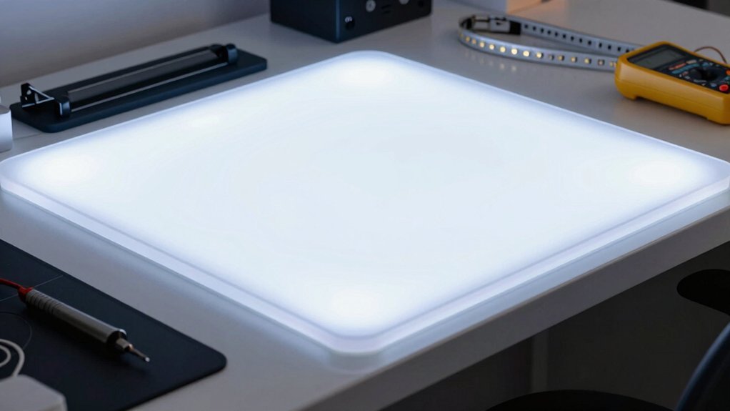
Want a uniform glow without hotspot glare? You’ll start by adding a diffusion layer over the LED array. Pick a diffusion material like 3 mm frosted Perspex or diffused acrylic; its translucent surface scatters point LEDs and evens the light. Cut the sheet to match the desk dimensions, then mount it with spacers or a thin frame so it sits directly above the strips but beneath the final top cover. Secure it firmly to avoid gaps that cause light piping or uneven brightness. For WS2814 RGBW strips, this diffusion material blends color transitions, cuts banding, and preserves color accuracy. You can also experiment with sand‑blasted surfaces for a softer look, but ensure the layer remains flat and stable for a seamless light field magnetic capabilities
Troubleshoot and Upgrade Your LED Desk
Where’s the problem? You’ve wired the LED strip, but flickering or dead zones still appear. First, verify data direction across each row—snake‑pattern wiring must stay consistent, or the WS2814 RGBW strip will lose sync. Next, double‑check that the ESP32‑based MagWLED‑1 controller is set to 12 V operation mode and that setMaxPower limits current to 5 V/1000 mA, preventing overloads. Finally, confirm the diffusion layer (frosted acrylic or epoxy) sits snugly under the top cover so light spreads evenly.
Verify snake‑pattern wiring, set controller to 12 V mode, limit current, and ensure diffusion layer fits snugly.
- Inspect data lines for correct snake orientation.
- Re‑flash firmware and set 12 V mode on the controller.
- Adjust setMaxPower to protect the LED strip.
- Replace or reposition diffusion material for uniform illumination.
Frequently Asked Questions
How to Make a LED Light Table?
You’ll solder the addressable LEDs into a grid, connect them to a USB‑C ESP32 controller, power the board with a suitable 5 V/12 V supply, then program and Bluetooth‑control animations via the app.
What Is the Best Wood for a DIY Desk?
You’ll get the strongest, most stable surface with hardwood like maple or oak; they resist warping, take finishes well, and hold hardware securely, making them ideal for a DIY desk.
Are LED Desk Lamps Worth It?
Yes, you’ll love the vibrant, customizable lighting; it boosts focus, reduces eye strain, and adds a sleek aesthetic. Just guarantee proper power management and diffusion to avoid hotspots and excessive heat.
Can You Build Your Own IKEA Desk?
Yes, you can assemble an IKEA‑style desk yourself—pick a flat frame, add a support grid, mount diffused LED strips behind a frosted top, route power and data neatly, then finish with wood veneer or acrylic.
In Summary
Now you’ve got a sleek, customizable LED desk that brightens your workspace and adapts to your mood. By following the steps—gathering materials, assembling the frame, wiring safely, flashing firmware, and adding diffusing material—you’ve created a functional, eye‑friendly surface. Keep an eye on connections, tweak the code, and upgrade components as needed. Enjoy the vibrant glow and the boost in productivity it brings.


Leave a Reply